 Eng
Eng  中文简体
中文简体Submit feedback
How to Adjust the Tension of a Side Bow Roller Chain Correctly
Update:10-04-2026
Posted by Admin
Content
- 1 Understanding Why Tension Matters in Side Bow Roller Chains
- 2 Tools and Safety Preparations Before You Start
- 3 Checking Current Chain Tension Before Adjusting
- 4 Types of Tensioning Systems on Side Bow Chain Conveyors
- 5 Step-by-Step Tension Adjustment Procedure
- 6 Tension Adjustment Reference by Chain Condition
- 7 Common Mistakes That Lead to Repeated Tension Problems
- 8 Recommended Tension Inspection Intervals
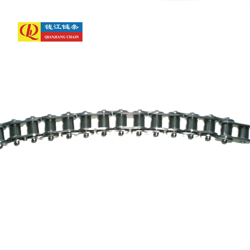
A side bow roller chain — also called a lateral flex chain or S-flex chain — is a specialized type of roller chain engineered to travel along curved horizontal paths, making it indispensable in conveying systems, bottling lines, packaging machinery, and material handling equipment where straight-line conveying is not practical. Unlike standard roller chains that operate in a single plane, side bow chains are designed with clearances and link geometry that allow them to flex laterally around bends. However, this lateral flexibility does not eliminate the need for correct longitudinal tension — in fact, improper tension in a side bow roller chain is one of the most common causes of premature wear, derailment, noise, and conveyor system downtime. This guide covers everything you need to know to adjust tension correctly and keep your side bow chain running reliably.
Understanding Why Tension Matters in Side Bow Roller Chains
Tension in a roller chain serves a dual purpose: it maintains positive engagement between the chain and the drive sprocket teeth, and it prevents the chain from sagging excessively on the return or slack side of the conveyor. For side bow chains specifically, correct tension is even more critical because lateral flexibility is achieved through controlled clearances between the inner and outer link plates and the rollers. When the chain runs too slack, these clearances allow the chain to shift laterally in an uncontrolled manner, causing it to ride up on guide rails, produce excessive noise, and wear the link plates and rollers unevenly.
Conversely, a side bow chain that is too tight loses its ability to flex around curves smoothly. Excessive tension forces the chain to drag against the outer guide rails at every bend, generating friction heat, accelerating wear on the chain's inner link plates and the guide track surface, and increasing the load on bearings and drive components. In severe cases, an over-tensioned side bow chain can cause the rollers to jam in the track, the drive motor to overload, or even chain breakage under shock loading. Finding and maintaining the correct tension — not too tight, not too slack — is the essential skill for anyone maintaining this type of conveying equipment.
Tools and Safety Preparations Before You Start
Before performing any tension adjustment on a side bow roller chain, gather the appropriate tools and complete the necessary safety preparations. Working on conveyor chains without proper lockout/tagout is one of the most serious hazards in industrial maintenance, and no adjustment procedure should begin until the machine is confirmed de-energized and secured against unexpected startup.
- Lockout/Tagout (LOTO): Isolate all energy sources to the conveyor — electrical, pneumatic, and hydraulic. Apply personal locks and tags to all isolation points and verify zero energy state before touching the chain or any drive components.
- Measuring Tools: A steel rule or tape measure for checking sag depth, a torque wrench for tightening tensioner lock nuts and take-up bolts to specification, and calipers for checking chain elongation if wear assessment is also being performed.
- Wrenches and Spanners: The appropriate open-end, combination, or socket wrenches to fit the take-up unit hardware on your specific conveyor model. Having both standard and metric sizes available avoids delays.
- Chain Wear Gauge: A dedicated roller chain wear gauge or pitch measurement tool confirms whether the chain has elongated beyond the replacement threshold before you invest time in tension adjustment — a worn-out chain will not hold proper tension regardless of adjuster position.
- Lubricant: Appropriate chain lubricant for your application (food-grade if required) to apply after adjustment, since tension adjustment provides an opportunity to inspect and lubricate the chain.
- Personal Protective Equipment: Safety glasses, cut-resistant gloves, and steel-toed footwear as minimum requirements when working around conveyor chains.
Checking Current Chain Tension Before Adjusting
Before making any adjustments, assess the current tension condition of the chain systematically. This step prevents unnecessary adjustment, identifies whether the chain has worn beyond acceptable limits, and gives you a baseline for how much correction is needed.
Measuring Chain Sag on the Slack Side
The most direct way to assess tension on the slack or return side of the chain is to measure sag — the vertical drop of the chain between two support points. On a horizontal conveyor, locate a section of the return run between support rails or idler rollers and measure the distance from a straight reference line (such as a taut string or the edge of a straightedge laid across the support points) down to the lowest point of the chain loop. For most side bow chain conveyors, acceptable sag on the return side is approximately 1–3% of the span between supports. For a span of 1000 mm, this means 10–30 mm of sag is the target range. Less than 10 mm suggests the chain may be over-tensioned; more than 30 mm indicates insufficient tension.
Checking Chain Elongation
Chain elongation from pin and bushing wear is the underlying reason tension increases over time and is also why a heavily worn chain cannot be corrected by tensioning alone. To measure elongation, lay the chain flat on a clean surface and measure the distance across a fixed number of pitches — typically 10 to 20 links — using a steel rule placed against the inner face of one pin to the inner face of the pin at the far end of the measured section. Compare this measurement to the nominal pitch multiplied by the link count. If the measured length exceeds the nominal by more than 2%, the chain has reached the end of its service life and must be replaced rather than re-tensioned. Attempting to tension a chain stretched beyond this limit simply shifts the elongated section around the drive sprocket, causing skipped teeth, vibration, and accelerated sprocket wear.
Types of Tensioning Systems on Side Bow Chain Conveyors
Side bow chain conveyors use several different take-up and tensioning designs depending on the conveyor length, chain pitch, and manufacturer. Knowing which system your conveyor uses determines exactly how tension adjustment is performed.
Screw Take-Up Units
The screw take-up is the most common tensioning mechanism on small to medium side bow chain conveyors. A bearing block holding the tail shaft or a tensioner wheel is mounted in a slotted frame and adjusted by turning a threaded rod — the take-up screw — which pulls the bearing block outward, increasing chain tension. Lock nuts or jam nuts secure the adjustment once the correct tension is achieved. Screw take-ups allow precise incremental adjustment and are simple to operate, but they require manual re-adjustment as the chain elongates during service life.
Spring-Loaded Tensioners
Spring-loaded tensioner arms or shoes maintain constant pressure on the slack side of the chain automatically, compensating for elongation without manual intervention between major maintenance intervals. The tension force is determined by the spring rate and preload setting, which are set during installation. If tension appears insufficient despite a spring tensioner being present, the spring may have fatigued, bottomed out due to excessive chain elongation, or the preload may need resetting by adjusting the spring compression length according to the equipment manufacturer's specification.
Hydraulic and Pneumatic Tensioners
Longer conveyors and higher-duty applications may use hydraulic cylinders or pneumatic actuators to apply a controlled, constant tension force to the chain take-up. These systems use a pressure regulator to set the tensioning force and automatically extend the cylinder as the chain elongates. Adjusting tension in these systems involves setting the regulator pressure according to the manufacturer's recommended tension force for the chain pitch and load condition, rather than measuring physical sag. A pressure gauge in the supply line to the cylinder provides direct verification of the applied tension force.
Step-by-Step Tension Adjustment Procedure
The following procedure applies specifically to screw take-up systems, which are the most commonly encountered type in side bow chain conveyor maintenance. Adapt the approach for spring or hydraulic systems as described above.
- Step 1 — Complete LOTO: Isolate all energy sources and apply personal locks. Verify zero energy state by attempting to start the conveyor and confirming no movement occurs.
- Step 2 — Measure existing sag: Record the current sag measurement on the slack side return run between two support points. Note whether the chain is too slack or too tight relative to the 1–3% of span target.
- Step 3 — Loosen the lock nuts: Back off the lock nuts or jam nuts on the take-up screws on both sides of the tail shaft equally. Always adjust both sides by the same amount to maintain shaft alignment perpendicular to the chain path.
- Step 4 — Turn the take-up screws: Turn both take-up screws by equal amounts — typically a quarter turn at a time — in the direction that moves the tail shaft or tensioner wheel away from the drive. Re-measure sag after each quarter-turn increment and continue until the sag falls within the target range.
- Step 5 — Verify alignment: After reaching the target sag, confirm that the tail shaft remains square to the conveyor frame by measuring the distance from each bearing block to a fixed reference point on the frame on both sides. Differences greater than 1–2 mm indicate misalignment that must be corrected by adjusting the take-up screws individually until both measurements are equal.
- Step 6 — Tighten lock nuts: Once alignment is confirmed, tighten the lock nuts on both take-up screws to the torque specified by the equipment manufacturer. Do not rely on hand-tightening — vibration during operation will loosen inadequately torqued fasteners, causing the tension to relax and the shaft to migrate.
- Step 7 — Lubricate the chain: Apply the appropriate lubricant to the chain before restarting. For side bow chains on food conveyors, use approved food-grade lubricant applied to the inner link plates and rollers along the full length of the upper run.
- Step 8 — Remove LOTO and perform a trial run: Remove all locks and tags, restore energy, and run the conveyor at slow speed initially. Observe the chain through all curves for smooth lateral flexing, absence of contact with outer guide rails, and quiet, consistent operation. Stop and re-inspect tension and alignment if noise, vibration, or tracking issues are observed.
Tension Adjustment Reference by Chain Condition
The following table summarizes the diagnostic signs, likely causes, and corrective actions for common tension-related conditions found during side bow chain inspection:
| Observed Condition | Likely Cause | Corrective Action |
| Excessive sag on return run | Insufficient tension or chain elongation | Advance take-up; check elongation and replace if >2% |
| Chain riding up on outer guide rail at bends | Over-tension or misalignment | Reduce tension; verify shaft and track alignment |
| Loud rattling or slapping noise | Too much slack allowing chain oscillation | Increase tension to lower limit of target sag range |
| Drive motor overloading | Excessive tension or chain seized in track | Reduce tension; inspect chain and track for jamming |
| Chain jumping sprocket teeth | Severe elongation or very low tension | Measure elongation immediately; replace chain and inspect sprocket |
Common Mistakes That Lead to Repeated Tension Problems
Even experienced maintenance technicians make errors when adjusting side bow chain tension that lead to recurring problems. Understanding these mistakes helps you avoid repeating them.
- Adjusting only one side of the take-up: Moving one bearing block further than the other skews the tail shaft, misaligning the chain relative to the sprocket and guide track. Always adjust both sides equally and verify shaft squareness after every adjustment.
- Over-tensioning to compensate for a worn chain: A chain stretched beyond 2% cannot be corrected by tightening. Over-tensioning a worn chain accelerates sprocket wear and risks chain breakage. Replace the chain instead of forcing it tighter.
- Checking tension only at one point: Side bow chains run through curves where the effective length of the chain in the track changes. Always check sag at multiple points along the return run, particularly before and after bends, to confirm even tension distribution throughout the system.
- Neglecting lubrication after adjustment: Tension adjustment moves chain links relative to one another and exposes dry metal surfaces. Applying lubricant immediately after adjustment reduces break-in wear and helps the chain settle to its adjusted tension more quickly and uniformly.
- Failing to re-check tension after the first run: New or newly adjusted chains settle under load during the first hours of operation. A tension check after the first two to four hours of running — once the chain has bedded in — is essential to confirm that the adjustment has held and no further correction is needed.
Recommended Tension Inspection Intervals
Establishing a regular inspection schedule for side bow chain tension prevents gradual drift from correct settings from developing into a failure event. The appropriate interval depends on the duty cycle, load intensity, and operating environment of the conveyor, but the following schedule serves as a practical baseline for most applications:
- After initial installation or chain replacement: Check tension after the first 4–8 hours of operation to confirm settling has not caused excessive slack, then again at 40–50 hours. New chains elongate most rapidly during the break-in period as machining marks on pins and bushings bed in.
- Monthly inspection: For conveyors running single shift in moderate duty conditions, a monthly tension and lubrication check is typically sufficient to catch developing issues before they cause problems.
- Weekly inspection: Conveyors running continuously, handling abrasive materials, or operating in wet or chemically aggressive environments should be inspected weekly, with particular attention to wear on the link plates and roller surfaces at curve sections where lateral loads are highest.
- Immediate inspection triggers: Any change in operating noise, visible chain sag or tracking deviation, increased drive motor current draw, or product spillage caused by chain movement should trigger an immediate unscheduled tension and alignment check rather than waiting for the next scheduled interval.
News
-
I. Introduction Conveyor systems form the backbone of modern industrial automation, enabling the eff...
READ MORE -
1. Introduction 1.1 Definition and Basic Concept of Coupling Chains Coupling chains are mechanical d...
READ MORE -
1. Introduction to Leaf Chains Leaf chains are a type of mechanical chain used in a variety of indus...
READ MORE
 +86-13805752016
 +86-571-82875104/82875108
 [email protected]
 No. 80 QianNong West Road, Xiaoshan District, Hangzhou City, Zhejiang Province,China
Copyright © Hangzhou Qianjiang Chain Industries Co., Ltd. All Rights Reserved.
|
 浙公网安备33010902004043号